
TR-42C1
Temperature Control Protection Relay with RS485 Modbus Communication


Features
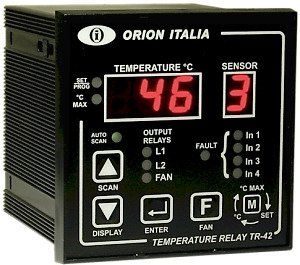
- Display of the actual temperature of the 4 RTD
- Display & storage of the highest temperature of each RTD
- 3 programmable output contacts from 0° to 220°C level 1, level 2 and FAN control
- Automatic and “Always ON” fan mode
- Alarm of TR-42 failure or PT 100 disconnection
- Automatic fan start every week (bearing protections)
- Insulated RS-485 communication port (Model TR-42C1 only)
Communication
Functions and Signals
DISPLAY: On the display “TEMPERATURE °C” (3 digits) you can observe the value of the temperature and program the settings; through the display “ SENSOR ” (1 digit) you can see the corresponding Pt Channel.
LED “SET/PROG”: If “on”, it indicates that the user is viewing the SET mode. If “flashing”, it means that the user is in the PROGRAM mode.
LED “ °C MAX”: If “on”, it indicates that the user is in the °C MAX mode.
LED “L1, L2”: If “on”, the temperature of one of the RTD have re ached the corresponding L1, L2 or FAN programmed threshold and the corresponding relay is active. If FAN led is flashing, the weekly fan activation function is active.
LED “In1, In2, In3, In4” : If “on”, the temperature of one of the corresponding RTD have reached the L1 or L2 programmed threshold and the corresponding relay is active. If “flashing”, the respective RTD has fault.
LED “FAN”: If “ON” the “always ON” mode is active and the FAN relay will be always active. If “Blinking”, the te mperature of one RTD reach the corresponding FAN programmed thre shold or the weekly fan activation function is active and the FAN relay is active.
LED “FAULT”: If “flashing”, indicates that the flashing “In1, In2, In3, In4”, has fault. The fault cause will be showed through the °C display when positioned bye the arrow buttons on the faulty sensor: ”Fcc” in case of short circuit and “Fco” for open circuit.
DISPLAY BUTTON: If pressed on the first position in any mode will execute a test to the display and leds. It is also used for changing views or for selecting programming values.
SCAN BUTTON: If pressed for 2 seconds in any mode the TR-42 will scan between each RTD temperature showing it on the display every 5 sec allowing the user to see all the temperatures automatically. To exit from the “auto scan” function, press any arrow button.
FAN BUTTON: it allows to switch between “always ON” or Automatic Fan Operation. In “always ON” mode, the Fan will be always ON and the led FAN will be ON. In automatic mode, the Fan will be ON and the fan led will Blink when one RTD reach the corresponding FAN programmed threshold; the Fan and the fan led will be OFF when temperature does not reach the corresponding FAN programmed threshold.
LED “AUTO SCAN”: If “on”, it means the user is in the AUTO SCAN mode.
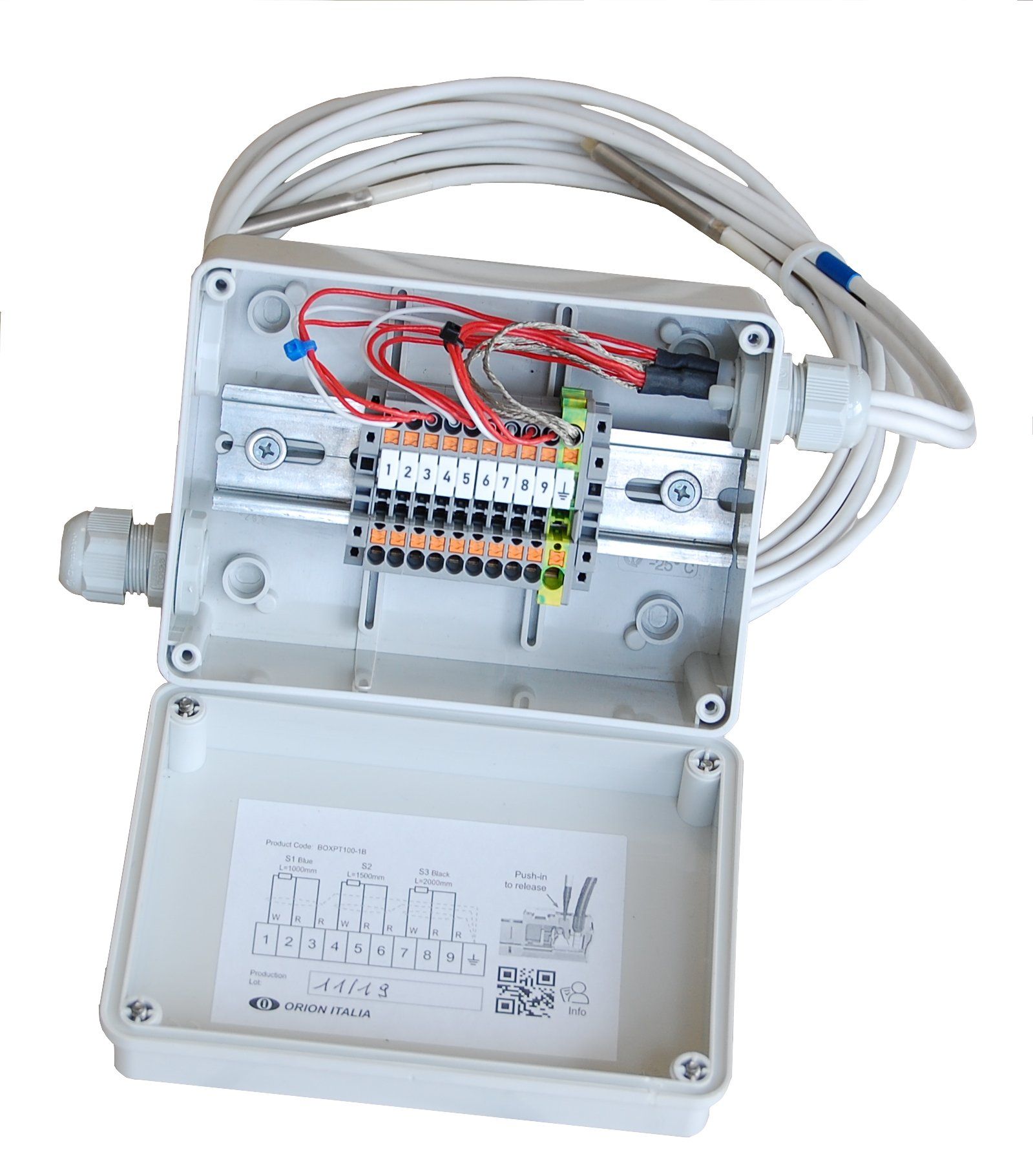
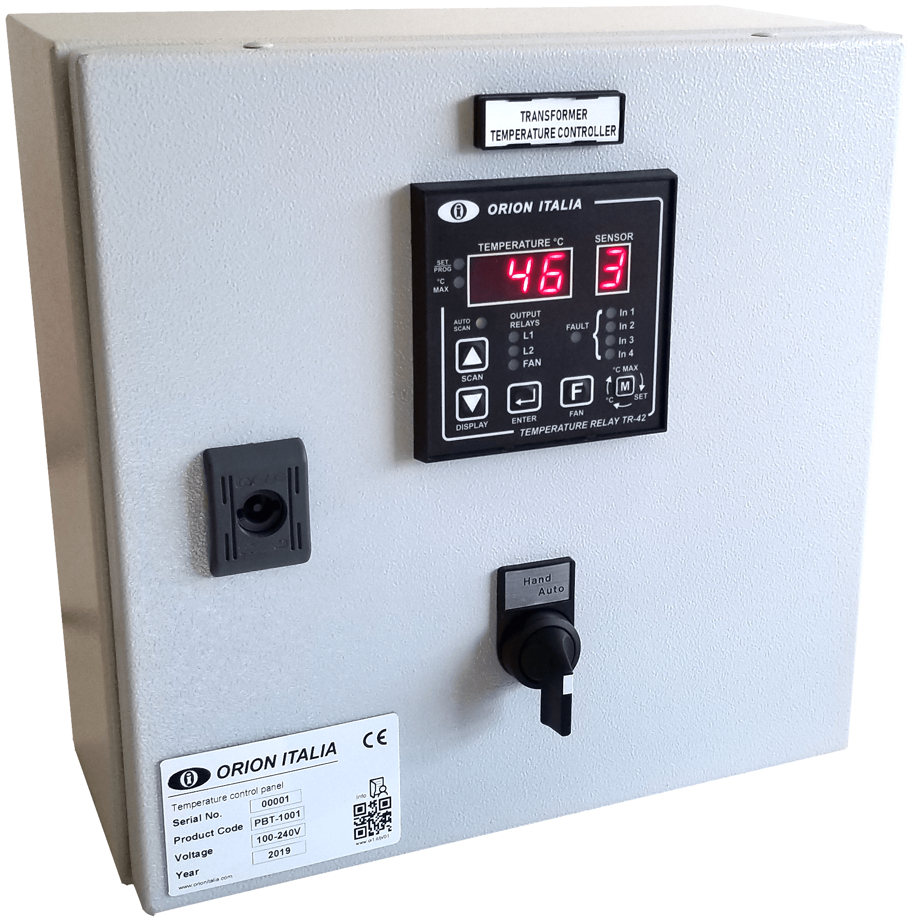
Accessories and solutions for the TR-42 Family